I bought a new bike computer recently (to go with my new bike, but that's another post). It's a Garmin Edge 305, and does everything I need it to, plus some extras. In particular, it's got a GPS on it. While this is a good way to keep track of speed and distance traveled, it can also give you a map, automatically trigger the lap counter at specific locations, show your progress against a previous workout or desired pace, etc. The only downside in the reviews I read was that the internal rechargeable lithium-ion battery would only last about 4-5 hours, which is fine most of the time, but is a bit short for those really epic rides or races.
The Garmin charges through a mini-USB port. I'd seen altoids-case battery USB chargers here and there on the net, and thought it'd be simple enough to build. But after looking at available designs, I was unsatisfied. The standard 3 terminal regulator, while really the only necessary component, has to bleed off a lot of heat and will drain a battery quite a bit faster than necessary. A switching power supply has the advantage of being quite a bit more efficient, but requires more components. I hadn't seen anyone try to make a teeny switching supply for USB, so it was into the abyss!
Design:
I started with my trusty Horowitz and Hill. If you mess with electronics, and don't have a copy of The Art of Electronics, just go get it right now. From there I went looking for parts at Jameco, and perused some switching IC specs. I ended up with a design based on the reference design of the switching IC I ended up using.

Parts:
1 - Altoids Gum tin. Flavor is up to you.
1 - 9V battery
1 - LM2672N-5.0 Switcher IC (National Semiconductor) - 290765
1 - 100 uF HT Electrolytic Capacitor - 330747
1 - 47 uF HT Electrolytic Capacitor - 158246
1 - .01 uF Ceramic Capitor - 15230
1 - 47 uH High Current Toroid Inductor - 371821
1 - Schottkey Diode - 177949
1 - USB socket (female) - 161023
1 - 9V battery clip - 11279
1 - small proto board
and jumper wires, solder, epoxy, electrical tape, etc.
Jameco part numbers and links included above.
Construction:
 I started by breadboarding the circuit. DC output of 5V, no discernible ripple on the oscilliscope, so it looked like it was going to work.
 Next I soldered it together on a proto board. I kept things really compact... I wasn't sure I'd be able to fit it in the Altoids tin. In particular the inductor takes up a lot of space. The 9V is in the shot for perspective, and the USB socket, while unconnected, lies to the left of the circuit.
 Next step was cutting the small section of proto board out, and getting the USB socket attached. I rounded the corners of the proto board as necessary to fit in the tin.
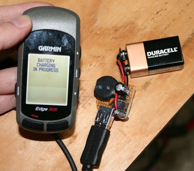 Hey look! It works!
 Here's the hole cut in the side of the Altoids tin for the USB plug. This was done with a dremel for the rough cut, and cleaned up with an ignition file.
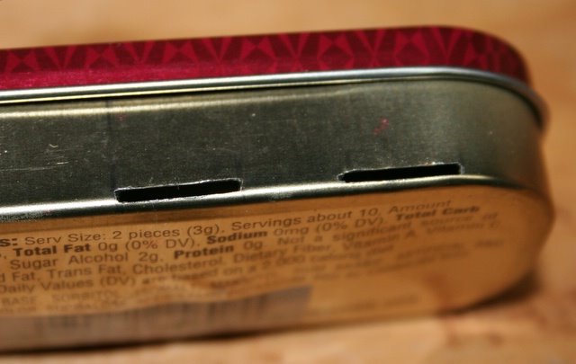 I put these two slots in the sides of the case (and matching ones on the other side) so that I could strap the case onto the handlebars of my bike. The slots are in the area that the battery sits inside the case.
 Epoxy time! I epoxied the proto board into the tin. Unfortunately, due to the tight fit, the USB plug had to extend a bit beyond the case. However, it is solidly epoxied in place. I also insulated the underside of the proto board with a layer of electrical tape (suspended in the epoxy) which prevents the circuit from shorting on the case.
 A closeup of the circuit end of the case.
 I used velcro cable ties for straps, threaded through the case. They also pad the battery a bit, which might have a tendency to rattle around just a bit. You can see how everything fits in the case in this pic.
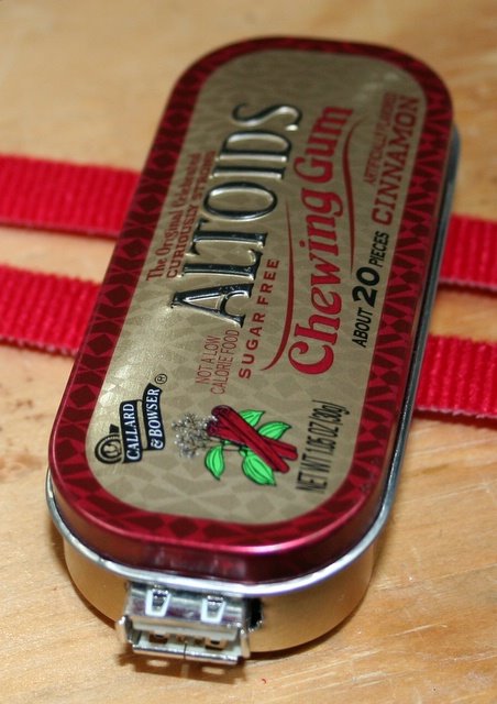 Hey, the lid even shuts. Actually, the lid shuts tightly enough that I'm not worried about it falling open accidentally. Those Altoids tins are well constructed. The metal case also acts as a faraday cage for that rapidly oscillating magnetic field in there...
 Strapped onto the handlebars.
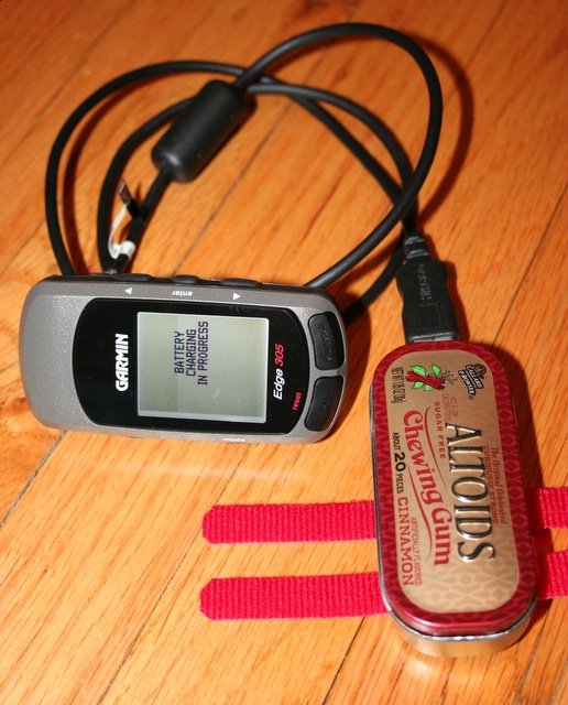 A final shot of it working.
Post-Mortem:
It works, and while I have not field tested it yet, I'll do that soon and post the results soon. I'm curious how long the 9V can power the circuit. I'm also curious about the efficiency of the circuit. In theory, it's up in the low 90s, but I'd like to test and find out.
Also, if I do this again, I'll probably go ahead and do a custom PCB rather than put it together on a protoboard. But we'll see.
Comments more than welcome!
2 comments:
Thanks, I missed that. Cut and paste error. Fixed now. The schottky I used is a 1N5817.
i am working on getting the parts, would a 50v schottky diode work? all i could find at radio shack was that. It was a 50v 1a micromini silicon diode.
Here are the specs:
Peak Inverse Voltage: 50V
Forward Voltage Drop(VF) at (If): 1.6V
Forward Current: 1A
Max Surge Current: 30A
Reverse Current at (PIV): 10MicroAmps
Post a Comment